Link Surcharging Definitions in SWMM 5

Subject: Link Surcharging Definitions in SWMM 5

The report or RPT text output file of SWMM 5 contains a table that lists the Surcharged Conduits during the simulation (Figure 1).

The 5 columns in the table are:

  1. Hours Both Ends Surcharged
  2. Hours Upstream End Surcharged
  3. Hours Downstream End Surcharged
  4. Hours Above Full Normal Flow
  5. Hours Capacity Limited

.the five columns are defined in Figure 2. Notice that if the midpoint of the link is full then the link and both end of the link are considered to be surcharged. If the midpoint is NOT full then the cross sectional area of the ends of the link determine wheter the ends of the link are considered surcharged. The end of a link can be considered surcharged based on either the depth at the midpoint or the cross sectional area at the end of the link.

Figure 1: The SWMM 5 Conduit Surcharge Table

Figure 2: The SWMM 5 Conduit Surcharge Table Definitions, the numbers in the 3rd column correspond to the columns in the Conduit Surcharge Table.

PID Control in SWMM 5 for an Orifice

Subject: PID Control in SWMM 5 for an Orifice


The blog http://swmm5.blogspot.com/2010/12/pid-control-in-swmm-5-for-type-3-pump.htmldescribes the Function getPIDSetting which returns the PID setting at each time step. The PID parameter set contains three values -- a proportional gain coefficient, an integral time (in minutes), and a derivative time (in minutes) which are kp, ki and kd, respectively. More about the theory of PID controllers can be found at http://en.wikipedia.org/wiki/PID_controller.


Here is an example PID Rule that will keep the node depth at 5 feet in a SWMM 5 model by changing the Orifice Setting. The Orifice setting opens and closes the orifice over time. The example file is attached in this blog. In this particular example, you can reduce the oscillations about the 5 foot rule level by lowering the integral time and derivative time coefficients in the PID control rule. An important note is that for Weirs and Orifices the setting is bounded to be between 0 and 1. If the Orifice or Weir cannot handle the upstream node inflow then the PID control will not be able to meet the depth goal in the node. For example, in the example file, an orifice depth of 2 feet is not enough to meet the upstream node depth goal of 5 feet but a 3 foot orifice is large enough for the PID control to meet its stated goal of 5 feet. The PID control will only work if the link doing the controller has enough flow and depth flexibility.


RULE PID_Orifice

; the PID controller adjusts the orifice opening to have a

; depth of 3 feet in Node 82309b

IF NODE 82309b DEPTH 5

THEN ORIFICE OR1@82309b-15009b SETTING = PID 10 -0.01 -0.01

; kp ki kd

PRIORITY 1


PID Control in SWMM 5 for a Weir

Subject:  PID Control in SWMM 5 for a Weir

The blog http://swmm5.blogspot.com/2010/12/pid-control-in-swmm-5-for-type-3-pump.html describes theFunction getPIDSetting which returns the PID setting at each time step. The PID parameter set contains three values -- a proportional gain coefficient, an integral time (in minutes), and a derivative time (in minutes) which are kp, ki and kd, respectively. More about the theory of PID controllers can be found at  http://en.wikipedia.org/wiki/PID_controller

Here is an example PID Rule that will keep the node depth at 3 feet in a SWMM 5 model by changing the Weir Setting.  The example file is attached in this blog.  In this particular example, you can reduce the oscillations about the 3 foot rule level by lowering the integral time and derivative time coefficients in the PID control rule. 

 RULE PID_Weir
; the PID controller adjusts the weir height to have a
 ;     depth of 3 feet in Node 82309e
 IF NODE 82309c DEPTH 3
 THEN WEIR WEIR1@82309c-15009c SETTING = PID 10 -.01 -.01
;                                           kp ki  kd  
PRIORITY 1 


PID Control in SWMM 5 for a Type 3 Pump

Subject: PID Control in SWMM 5 for a Type 3 Pump

Figure 2 shows the code in Function getPIDSetting which returns the PID setting at each time step. The PID parameter set defines the degree of control. The PID parameter set contains three values -- a proportional gain coefficient, an integral time (in minutes), and a derivative time (in minutes) which are kp, ki and kd, respectively. More about the theory of PID controllers can be found at  http://en.wikipedia.org/wiki/PID_controllerand shown in Figure 3.

Here is an example PID Rule that will keep the node depth at 3 feet in a SWMM 5 model.

RULE PID1
 ; the PID controller adjusts the flow in the pump to have a
;     depth of 3 feet in Node 82309e
IF NODE 82309e DEPTH <> 3
THEN PUMP PUMP1@82309e-15009e SETTING = PID  10     -1  -1
;                                                                                 kp     ki   kd
PRIORITY 1


Figure 1:  SWMM 5.0.021 Simulation Results

Figure 2:  Source code for getPIDSetting in SWMM 5.0.021

Figure 3:  Image source for the Block Diagram of a PID Controller Pid-feedback-nct-int-correct.png

Total Surcharge Time vs Total Time Above Rim Elevation in InfoSWMM

Subject: Total Time Above Rim Elevation at a Node

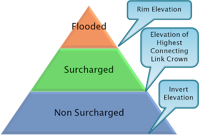
1. Total Surcharge Time is the total time above the crown of the highest connecting pipe to a node.

2. Total Time Above Rim Elevation – this is the flooding time of the node and it includes flood time as well as ponding time. You can find this in the Junction Summary Report of InfoSWMM under the column Total Flood Time. The Total Flood Time should be less than the Total Surcharge Time as the depth in the Node is higher.

  1. A node is flooded if the node depth equals the node rim elevation – the flooded time is the total time excess flow is coming out the top of the manhole,
  2. A node is flooded if the node depth is above the rim elevation and you are using the Surface Ponding Option – the flooded time is the ponding time
  3. A node is flooded if the node depth equals the node surchage elevation – the flooded time is the total time excess flow coming out the top of the surcharged manhole.